Direct Altium-Onshape Connector for ECAD-MCAD Collaboration
Synchronizing electronic PCB layouts with mechanical enclosure assemblies to eliminate tolerance errors and streamline hardware release reviews.
Bridging Electrical Layouts with Mechanical Enclosures
Bi-Directional Parametric Data Flow
Hardware development frequently suffers from disjointed communication between circuit board designers and mechanical engineers. Relying on intermediate neutral files such as STEP or IDF causes loss of metadata, missed keep-out changes, and undetected thermal interferences until physical prototyping.
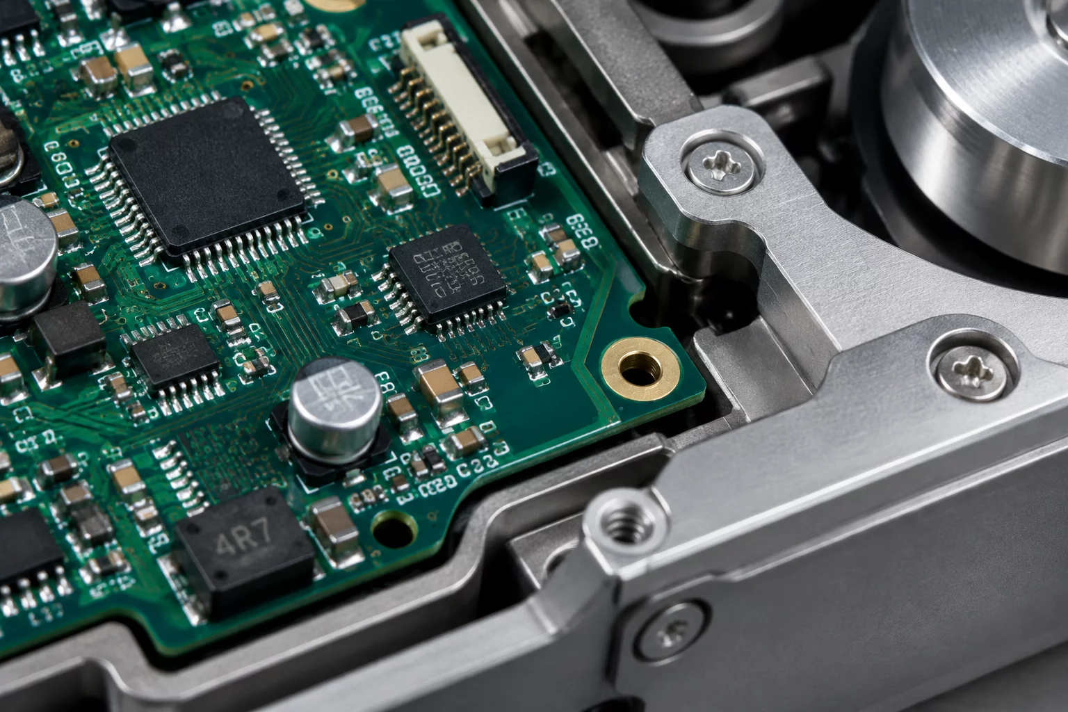
The direct connector links Altium Designer with Onshape cloud documents, ensuring board outlines, mounting holes, component clearances, and connector orientations synchronize in real time across both domains.
Review Integration Protocols
Discover structured checkpoint templates designed for cross-discipline electromechanical reviews.
Overcoming the Disconnect in Hardware Packaging
Electrical and mechanical engineering teams frequently operate within isolated design environments. PCB layout specialists work inside Altium Designer, manipulating high-density traces, via arrays, and component footprints. Meanwhile, mechanical engineers build structural enclosures, thermal management channels, and mounting standoffs inside Onshape. Traditionally, sharing geometry required manual exports to neutral file formats such as STEP, IDF, or DXF.
These static transfer methods introduce severe friction. Every design change necessitates generating, emailing, and importing intermediate files, stripping parametric relationships and version history. When a board outline shifts or an electrolytic capacitor increases in height to meet power demands, mechanical models become outdated without notice. The resulting packaging errors remain invisible until physical components arrive on the assembly floor.
“Direct cloud synchronization converts electromechanical reviews from an anxious end-of-stage gate into a continuous, real-time verification process.”
— Lisa Ray, Electromechanical Systems SpecialistThe direct connector eliminates manual exports by binding Altium layout databases directly with Onshape cloud documents. Changes made to board perimeters, mounting hole coordinates, and component placements propagate across both platforms with complete parametric fidelity, ensuring continuous alignment throughout every revision cycle.
Five Core Review Perspectives for Integrated Assemblies
A successful cross-functional design review requires examining the electromechanical assembly through distinct, domain-specific evaluation windows before authorizing fabrication:
-
Electrical Layout Perspective Are all critical keep-out boundaries, high-speed trace corridors, and copper ground plane clearances preserved after mechanical mounting adjustments?
-
Mechanical Enclosure Perspective Do connector ports, light pipes, and screw boss heights maintain precise nominal clearance and worst-case tolerance stack-up margin?
-
Thermal Management Perspective Are heatsink interfaces, thermal interface material (TIM) contact surfaces, and convection airflow pathways unobstructed across high-dissipation components?
-
Manufacturing & SMT Assembly Perspective Is there adequate automated pick-and-place clearance around board edges, tall capacitors, and polarized terminal blocks during panelized reflow?
-
Operations & Serviceability Perspective Can field technicians replace modular connectors, access programming headers, and inspect board status LEDs without disassembling primary structural fasteners?
Framing review sessions around these explicit questions prevents vague feedback and establishes decisive criteria for approving electromechanical baseline releases.
Connector Architecture & Integration Parameters
The operational framework relies on direct cloud synchronization mechanisms designed to sustain cross-domain parametric coherence:
| Synchronization Method | Bi-directional cloud API linking Altium 365 projects to Onshape Part Studios and Assemblies |
|---|---|
| Supported Geometry Elements | Board outlines, cutouts, mounting holes, 3D component models, keep-out volumes, and copper layer profiles |
| Revision Tracking Mode | Automated release tagging with visual differential comparison across branches |
| Interference Detection Speed | Sub-second dynamic clearance checking directly within the browser-based CAD environment |
Request Review Case Consultation
Structure your internal engineering reviews with isolated perspectives and tailored inquiry protocols.